 Contents of this
side:Contents of this
side:
Contents of this
side:Contents of this
side:|
|
Terms of delivery |
|
|
information on claims |
|
|
Certificates and declarations |
|
|
How to buy at our company |
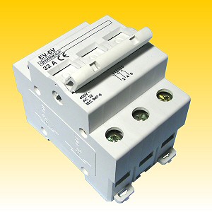
They are intended to be built into the switchboards attached to the strip DIN 35 mm.
Together with circuit breakers and Residual Current Devices BONEGA®EV-P6 as well as other devices, these switches create an optimal combination of instruments for any modern solution of wiring systems. The switches are designed at the same boxes, as the circuit breakers are - connected together their appearance is very aesthetical. The switches are manufactured both as single-pole and double-poles ones.
The visual signalling of ON or OFF positions corresponds to that of the BONEGA® circuit breakers, namely in colour marking of the switching lever position
ON - red ![]() I -
ON
I -
ON
OFF - green ![]() O - OFF
O - OFF
With their construction and technical parameters, the switches BONEGA®EV - V are in compliance with the present world level.
They are marked with the logo BONEGA® and manufactured in accordance with the standard IEC 947 - 3.
| Technical data | |
| Number of poles : | 1,2,3,4 |
| Nominal currents : | 16,25,32,63 A |
| Nominal voltage : | 1 P (pole) ~ 230/400 V 50/60 Hz 3 P (poles) ~ 400 V 50/60 Hz |
| Category : | AC 22 |
| Protection : | IP 20 for separate switch- with its design, it protects against a dangerous finger touch and against small foreign objects; it is without any protection against water leakage (water protection is to be solved with design of the switchboard casing) |
| IP 40 for built-in switch- with its design, it protects against a dangerous finger touch and against small foreign objects; it is without any protection against water leakage (water protection is to be solved with design of the switchboard casing) | |
| Max. environment temperature: | -40 °C |
| Max. environment temperature: | 125 °C |
| Ambient temperature: | -5 °C to +40 °C in compliance with the CSN EN 60898 |
| Calibrating temperature: | +30 °C |
| Input terminals: | clip terminals (with barrier) with patent blocking which avoid the conductor to be put in incorrectly, the input and output can be changed, different terminal cross-sections up to ln 32 A - 25 mm2 and above ln 40 A - 35 mm2 enable more conductors as well as interconnecting strips to be bonded |
| Terminal protection: | IP 20 !!! |
| Tightening moment of terminals: | 2 Nm (combined slotted-head screw) |
| Fastening: | by means of a quick-fastening mechanism onto the carrying DIN strips EN 50022, width 35 mm or even onto a flat surface by means of screws |
| Operational position: | arbitrary |
Input or output can be connected both onto the upper and lower terminals without impairing the function of the switch. The mounting is thus easier and the distributions at the switchboards can be more variable
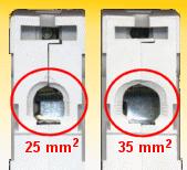
You will appreciate the clamp cross-section of 35 mm2 with all nominal values of the circuit breakers above 40 A, when mounting any bigger cross-sections of the conductors which must be dimensioned for higher power inputs. You do not need to solve such problems by means of additional terminals on which contact resistances could occur.
 - Layout of the
terminal with blocking barrier
- Layout of the
terminal with blocking barrier
It is an unique solution avoiding the problems which occur during assembly, when it is not possible to put the conductor under the terminal. That principle excludes frequent claims and (latent) mounting defects which often occured only by the users and the manufacturers of the switchboards incurred additional expenses (mainly transport expenses) for these defects to be removed "easily".
Our easy structure is based on the fact that each terminal has in its bottom part so-called "flat barrier" which - whe tightening the screw - occurs gradually at the entry hole into which the conductor shall be put in, and avoids the conductor to be put under the terminal clip - in that case would come to a fixed interconnection between the input or output of the circuit breaker.
The clip terminals themselves have in their bottom part also the cross grooves which avoid the conductor to be taken out from the terminal because being tightened, the conductor sinpce. into the grooves. Simultaneously, the transmission area gets large thus the the contact resistances are limited considerably
The clip terminals are seated in the switch covering so that the screws cannot fall out from the circuit-breaker body, even if they are fully screwed out from the terminal. This advantage has been reached because the diameter of the hole for a screwdriver is less than the diameter of the screw head. The screw head has been modified both for cross and flat screwdriver
onto the strip DIN EN 50 022 (width - 35 mm, thickness 0,8 - 2 mm)
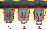
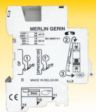
The pawl arrest in side positions facilitates both mounting of switches onto the DIN strips and their redismantling
Position Nr. 1 pursuant to the above figure is the ON position. At this position, the circuit breaker is hung on the boss in the upper part (see position A) of the DIN strip and with its bottom side, it touches the DIN strip by the chamfered area of the arresting pawl. If the circuit breaker is pressed from the front (user´s) side only by hand, the pawl moves outwards but not to the side - switched-off arrest position but it only gets over the edge of the DIN strip and without any assistance of other instrument, the pawl locpce. itself on the DIN strip - position Nr. 2
![]()
When dismantling, when the arresting pawl of the switch is in the position Nr. 2, it has to be moved to the position Nr. 3 by means e.g. of the screwdriver which is put through the pawl opening and pulled-half outwards where the pawl remains arrested and the screwdriver can be removed. You appreciate this advantage mainly when dismantling the more-poles circuit breakers when you need only one instrument for de-arresting without using it during the entire dismantling from the DIN strip, because the pawls can be pulled-half out to the side positions
Especially when repairing the old switchboard, you will appreciate the advantage which enables you to attach our switches onto a flat area even without using the DIN strips. This possibility does not require any modification of the switch. You can attach the switch, as follows: screw a flat-headed screw into the required place, leave a gap of approx. 5 mm between the screw and the flat area. Take the switch which bears a special cut-out in its upper part and put it onto the screw prepared. In the lower part, slip out the arresting pawl to the side "opened" position and through an opening in that pawl fasten the switch to the flat area by means of the other screw.
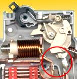
 This unique principle of the contact snap-action schwitching consists in following
three stages: during the first stage, even during a very slow "streching" of the
switch lever, the contacts are inside the switch brougth nearer to each other to
the distance of approx. 1,5 mm; the next motion of the lever leads to the second
stage, i.e. prestressing at the spring mechanism when the contacts are not brought
nearer to each other more; after a certain prestressing comes to the third stage
which is a strong switching of inside contacts (the fixed contact is straight while
the movable one is round). This switching is thus fully independant on the speed
of the lever motion. This principle offers the following advantages:
This unique principle of the contact snap-action schwitching consists in following
three stages: during the first stage, even during a very slow "streching" of the
switch lever, the contacts are inside the switch brougth nearer to each other to
the distance of approx. 1,5 mm; the next motion of the lever leads to the second
stage, i.e. prestressing at the spring mechanism when the contacts are not brought
nearer to each other more; after a certain prestressing comes to the third stage
which is a strong switching of inside contacts (the fixed contact is straight while
the movable one is round). This switching is thus fully independant on the speed
of the lever motion. This principle offers the following advantages:
a) the contacts can never burn-out (even with a very slow motion of the switch´s lever) and impair the whole switch
b) through a strong switching of contacts, the perfect contact point excluding any fault power transmission is provided, especially for low values of nominal current
c) pitting of contacts is limited to a minimum
d) the total lifetime of the circuit breakers is extended considerably
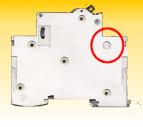
At the end of the manfatucture process, after a lot of tests for all the parameters, the plastic parts are joined together by means of ultrasound. This procedure ensures that the switch cannot be disassembled. This imaginary "ultrasonic rivet" results in welded plastic joins within 15 mm from the centre thereof. This solution excludes any interference of the users with the structure without damaging the casing.
The lever can be sealed because of openings in both guiding walls of the switch-off lever. Through these openings, a sealing wire can be fed. This sealing wire passes also through a groove at the movable lever. This groove has been engraved in both positions (OFF and ON positions) and it disables the motion of the lever itself.
Visual indication of the switched-on or switched-off condition of the switches is ensured by colour marking of the lever positions.


ON - red ![]() I -
ON
I -
ON
OFF - green ![]() O - OFF
O - OFF
The link-up of plenty accessories is solved by a very easy shutting-down which is possible to do on both sides of the switch. On the left and right sides, the opening is sticked over with a plastic sticker. To that opening a movable mechanism is linked-up inside - by means of the interconnecting element either the lever position is indicated or the lever is controlled therewith.
The high quality is given both by suitable materials and structures, and mainly by the thourough check-out:
![]()
On its bottom side, every switch is stamped by signs describing the characteristics, nominal current value, month of manufacture (since the beginning of the production - capacity up to 99 months) and number of the individual worker who has assembled the product. In this way, the workers are motivated to bear their liability for their labour. The fact is also important for obtaining the Certificates ISO 9001 and 9002.
- quick and flexible adaptation of the production to the customers´ requirements - an easy process with simultaneous production of several types. Monthly capacity of one shift is approx. 20.000 pcs. poles. We prepare a new check-out equipment controlled by the computer, which enables a signifcant increase of our production capacity.

The cases are intended for 12 modules so there are either 12 pcs. single-pole switches, or 4 pcs. three-poles switches (total weight of circuit breakers in one case amounts to approx. 1,3 kg).
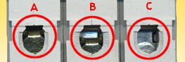
If there is only one switch type in the case, one side of the case is bar-code labeled (see Fig. A) descibing especially the type, characteristics, nominal current value and number of pieces.
If there are more types in one case, types and number of pieces are marked on the label (see Fig. B) - to be added manually, when packing. We are sure that you appreciate this type of packing not only when collecting the delivered goods, but even when mounting.
This advantage is given both by available stock of the most asked types and also by the fact that the products are manufactured at the premises of our company. This enables a good and immediate communication between the manufacture and sales departments. For fast deliveries, we use mainly the service of so-called Profi balík (parcel). This system delivers the parcel to your address mostly within 24 hours and for very good prices (e.g. delivery of the switches at the rate of 10.000 CZK excl. VAT with the total weight of approx. 15 kg from Sudomerice nad Moravou to As represents about 133 pcs. of single-pole or 46 pcs. of three-poles circuit breakers. The price for PROFI PARCEL delivery amounts only to CZK 92,00; i.e. 1 pce. of the single-pole switch is loaded by 0,69 CZK for transport, and 1 pce. of three-poles circuit breaker 2,00 CZK for transport - see detailed price list - reference: left scroll-on- "how to buy").
To give you an opportunity of no or only low stock we offer deliveries exactly in accordance with your orders - not conditioned by purchases of whole packagings. To facilitate these purchases by means of facsimile or e-mail orders you can find at these sides forms (see reference - left scroll - "how to buy"), which can be printed-out by your purchase departments, copied and just completed by number of pieces you need. Than you can send it per fax or e-mail. Of course, we are ready to accept your phone orders. We prepare the Internet shop for you
|
Range of goods |
|||
|
Order Code |
Description |
Quantity |
Packing pcs./case |
| 05-1016001 | switch 1P 16A | 1 pce. | 12 |
| 05-1025001 | switch 1P 25A | 1 pce. | 12 |
| 05-1032001 | switch 1P 32A | 1 pce. | 12 |
| 05-3032001 | switch 3P 32A | 1 pce. | 4 |
| 05-3063001 | switch 3P 63A | 1 pce. | 4 |
Export Manager: Michal Hudeček, tel: +420 605 518 724, [email protected]
Sales Department: - Mrs Adriana Jamná, fax +420 518 335 216, email : [email protected], 696 66 Sudoměřice nad Moravou 302
|
|
|
Products | About us | Customer support | Become our partner | Certificates & declarations | Contacts | Site map |
|
|