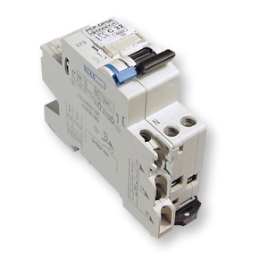
Quicker installation and easier operation


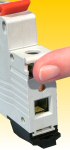
1. FAULT INDICATION BY A LEVER POSITION
At first sight you can distinguish if a
DPN has been switched-off by the user or
by a short-circuit or overload
 top top
|
If a DPN is switched-off by the user, the lever
moves from the most upper position (3 = ON) to the extreme lower
position (2=OFF). A follow-up switch is led directly from the OFF
position to the ON position.
WARNING:
The DPN is able
to indicate a fault within a circuit, which has been caused by
short-circuit or overload. In that case, the lever falls down only into
the central position. When moving the lever upwards, it does not put any
resistance, so it seems to have a defect mechanism.
NEVERTHELESS, IT IS NO DPN – FAULT!
The task of such condition is to draw the user’s attention to the
fact that the DPN protective system had to reply on any outside matter
(short-circuit, overload). In that case, it is necessary to trace the
cause.
You can renew the DPN activity in the following way:
- at first, the control lever has to be moved from the central
position into the lower position (position 2 in the picture). When
moving, you must overcome a little resistance put by the internal
mechanism. It comes to the rearrangement (clicking) of the mechanism.
In this lower position, the mechanism is ready for the follow-up
switching.
- then, the lever is moved from the lower position into the upper
position (position 3 in the picture). During that motion, you can
recognize an usual resistance known by a normal switch-on of a device.
.
|
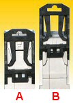
2. Locking Bar
A conductor will never be connected
incorrectly.
|
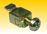
Terminal with locking bar:
|
|
Position A
– fully opened terminal
Position B
- the conductor begins to be tightened into the terminal
Position C
– partially tightened terminal, when the space underneath the terminal is
gradually closed by the locking bar
|
The design has been based on the fact, that every terminal has a so-called
“flat locking bar” in its movable bottom part. This locking bar is ejecting into
the space underneath the terminal, while the screw is being tightened. This
process avoids the conductor to be put-in under the terminal’s stirrup (as
happens by other DPNs) whereby it would not be possible to tightened the
conductor into the terminal.
A unique solution avoids the difficulties with connecting the conductors onto
a DPN. This principle excludes the possibility to place the conductor under the
terminal by mistake. In that case, the terminal would be tightened but,
unfortunately, without a conductor. If that mistake is not discovered during
installation by other DPNs, latent claim defects occur frequently. Such defects
occurred mostly at the end user (a conductor could be in contact with the
terminal but under a higher loading of the circuit, it burned-out and the
circuit was interrupted). The switchboard manufacturers had to bear additional
expenses for very „simple“ removal of such defects.
The above solution does not only avoid claims but it makes the installation
faster and contributes to the reliability.
top
3. Two-Line User's Inscription
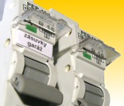
Even if the
cover plate of a switchboard has been removed, you can still see which circuit
is protected by the DPN.
Each pole is equipped with an aesthetic transparent swing cover placed above the
switching-off lever. Under that cover, there is a paper two-line inscription
label put into slots. It is also possible to write on the plastic surface. The
cover has an arrestment in the upper open position.
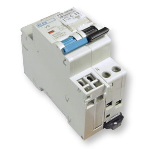
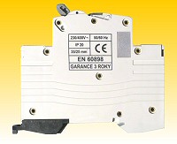
4. Convenient Short Dimensions
There is more space for connecting
the conductors on the switchboard.
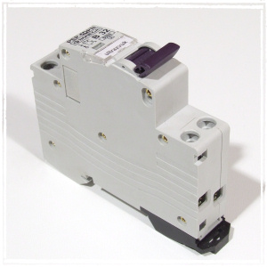
 The
extraordinary small dimensions (especially the height is only 81 mm) rank the
DPN BONEGA® P-E-P to the smallest ones worldwide within the category of the
breaking capacity up to 6 kA.
The
extraordinary small dimensions (especially the height is only 81 mm) rank the
DPN BONEGA® P-E-P to the smallest ones worldwide within the category of the
breaking capacity up to 6 kA.
- the total depth from the pawl incl. the lever in OFF position is 73,23 mm
- the total depth from the DIN strip incl. the lever in OFF position is
67,23 mm
- the total depth from the DIN strip up to the surface is 61,6 mm
- the total height of the body is 81 mm + projecting pawl in operational
position: 5,2 mm
- control part’s height is 45 mm
- module width 17,6 mm
- user’s inscription (A): width 15,4 mm x height 6,2 mm + thickness 0,3 mm
In the switchboard (in the covered part), remains more space for leading and
connecting of conductors. This property can be appreciated especially when using
those DPN in small plastic household switchboards.
top
5. Casing Resistance to Gaping Upon Terminal Installation
There is no gaping of the DPN
casing or cross threading of
the terminal in the casing.
|
It is a relatively usual problem on other DPN´s – upon
an excessive screwing-up of the terminal, the casing opens or the
terminal crosses in the casing. On some DPN´s, even the joints and thus
the circuit are broken. |
It is avoided on the DPN´s BONEGA® P-E-P by means of:
- plastic guides for the movable parts of the terminal, which has been
chosen properly
- press-pieces in the casing body
- places for rivets, chosen properly
- plastic pins (the casing has no butt joins)
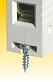
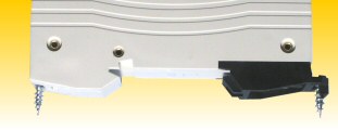
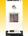
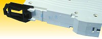
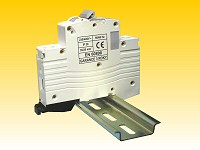
6. Attach the DPN onto a Flat Surface without DIN Strip
No problem in assembling to an old
breaker box.
|
|
|
|

Play animation
|
|
You will appreciate that advantage – a possible attachment of our
DPN
directly onto the flat surface without using the DIN strip - especially when
repairing old switchboards. This possibility do not require any modification of
the DPN.
How to do it:
- Screw a flat-headed screw into the flat area at the required position.
Leave that screw at a distance of approx. 5 mm from the surface (not
fully screwed).
- Onto the prepared screw put the DPN which has a corresponding cut in
its upper part.
- Draw out the arresting pawl to its final „open“ position in the bottom
part and then fasten the DPN by another screw to the flat surface through a
hole in this pawl.
The connection created in such a way is unusually strong.
|
top
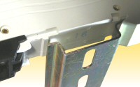
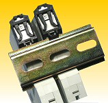
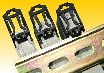
7. Increased Vertical Stability on the DIN Strip
When tightening the
terminals,
the DPN on a DIN strip will be straight.
|
This news on the DPN BONEGA® P-E-P is a very essential
improvement of vertical stability, while the conductors are connected to the
device. When drawing up the terminals, the DPNs tend to incline and it is
necessary to “pre-stress” them manually.
The high stability has been reached by a plastic stop on the DPN bottom.
After attachment of the DPN onto a DIN strip, this stop functions as the
“contra-pressure” (with the torsional stress of the DPN´s body). In contrast
to the competitors, the movable pawl has only the holding function.
The other hand does not have to engage itself with “pre-stressing” of the
DPN and can be concentrated only to hold the conductor to be connected.
This measure accelerates the installation and makes is easier
|
top
8. CONNECTION OF INPUT OR OUTPUT FROM BOTH SIDES
A possibility to connect the input as
needed.
Input or output can be connected both onto the upper and lower terminals
without impairing the function of the DPN in any way.
Through this advantage, the mounting is easier and the distribution arrangements
at the switchboards can be variable.
You will appreciate it especially in the switchboards with a multi-row
arrangement – you can connect the input between two rows (saving of conductors
and time)
9. Large Terminals
Even a big cross-section of the
conductor
will not surprise you.
|
Within the entire range of nominal currents´ values (up to
32 A), it is possible to use a conductor with a cross-section up to 16 mm2
for a full conductor and 11 mm2 for a stranded conductor.
The emergency solution by some additional terminals, when the contact
resistances can occur, does not take place.
top
|
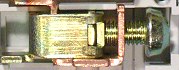
10.
Strong Design of Terminals
Impossible to strip the threads even
with excessive stress.
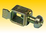
The movable terminal has been made of one piece. In contrast to other DPN´s, the
joint has been solved by means of an overlapping and not by a so-called “puzzle
joint”. Through this overlapping, there goes a screw. It has a double thread
length available, which restricts the breaks – “stripping” the thread
essentially. The possibility to break it when being mounted is fully
excluded even if the torsional stress allowed by the standard is exceeded. (more
than 2 N.m)
The clip terminals themselves have in their bottom part also the cross
grooves which avoid the conductor to be taken out from the terminal (after
being drawn up, the conductor sinks into the grooves). Simultaneously, the
contact resistances are limited. (because of the enlargement of the
transmission area the burning of the conductors is not possible).
The junction of a conductor and a DPN is very rigid and reliable.
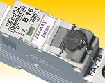
11. Locking Protection
The BONEGA® P-E-P DPN´s cannot be locked
from the outside.
This property protects the electro installation companies
against claims, which are caused by the end user, who can be proved wrong with
difficulties.
As the most products, also the DPN´s BONEGA® P-E-P has an
indication of the contact conditions. That indicates a real contact condition
and not only a position of the switch-on lever. In case of “sintered” contacts
and switched-off lever, the user is clearly informed about flowing current. As
the only ones, our DPN´s have that indication covered with a transparent
plastic sight-glass with a lens (magnifying) effect.
Reasons:
-
Because the indication is closely connected with a movable
contact, it happens on other DPN´s that the movable contact is locked
through the indication by means of a toothpick or a matchstick; thus the
complete thermal and short-circuit protection of a DPN is out of function.
It is not possible to do that on the DPN BONEGA® P-E-P, just because of that
transparent sight-glass
-
Dust protection
The DPN is equipped with a colored indication of contact
condition, which is independent on the lever position, and it depends just on
the real contact condition. In addition, this indication is protected against
dust penetration into the DPN by a transparent plastic cover with magnifying
effect.
top
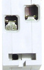
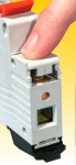
12. EASY LINK-UP OF THE ACCESSORIES ONTO A DPN
An easy and fast connection of the
accessories.
The plentiful accessories can be linked-up on the left side of the DPN. The
interconnection of the accessories with the DPN is done, as follows:
- 1. Remove the grey self-adhesive plate, which covers the interconnecting
hole on the DPN´s left side (with nail or screwdriver) in accordance with the
type of the accessories.
- 2. Set up the DPN into the OFF position
- 3. With an easy “snapping” into place without any tools, connect the
accessories to the DPN.
The DPNs can be connected with plentiful accessories (low-voltage release,
voltage release, auxiliary contacts etc.). All those elements extend the
application of the DPNs by overvoltage or undervoltage protection, control,
regulation, remote control, remote indication of switch-on and switch-off
positions of a DPN, programming and measurement. Those combinations enable the
DPNs to be applied for the control of complicated automation processes.
These elements can be mutually interconnected (e.g. DPN + undervoltage
release + auxiliary indicating contact etc.), thus they can form different
combinations
top
13. ARBITRARY INSTALLATION POSITION
The operational position without
influence
on the safe function.
The construction and seating of an ejecting coil for short-circuit release
affect the DPN function in various positions almost solely. In principle the
question is if the weight of the coil core helps or limits the kinetics of the
coil’s motion in different positions, and if the running of movable parts cannot
be violated, or if a crossing cannot occur whereby the e.g. coil’s core or
switching-off mechanism motion could be disabled. This result can exercise a
significant influence on the fact if the DPN in an inconvenient position does
not switch-off sufficiently fast in case of a short-circuit, or if it does not
react at all, or if it changes its characteristic curve.
It is excluded in case of our DPNs because we have managed it in following
way:
1) by design:
The design of the electromagnetic high-speed release with ejecting cage for
short-circuit protection has been solved so that it has not any adjustable
element. Its characteristic is given by cross-section of the copper wire of the
coil, by number of threads and spring pre-stressing in the core. This solution
thus excludes that our DPNs could change their presented characteristic curve by
a fall, shock or bedding in another installation position.
The DPNs BONEGA®are protected against avoiding the short-circuit release to
be put out of service by a suitable seating of the structure elements,
especially of the ejecting coil which is seated in a unique “cradle” (see
“guaranteed reliability”). This design has excluded the possibility to misalign
and consequently to seize the movable core at the coil.
2) by seating itself
The ejecting coil is seated in the case so that the core’s motion direction,
when ejecting, goes against the gravitational force (also upwards). From the
resistance’s point of view, it is the most unsuitable position. In this
position, the DPN´s parameters are set up. Therefore, any other installation
position is only for the benefit of switch-off rate. The gravitational force
helps for safety in any other positions.
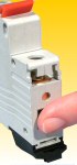
14. Quick Removal of the DPN from the DIN Strip
You need not dismantle the
interconnecting strip.
|
A unique auxiliary mechanism allows an easy removal
of a DPN. |
Play animation
|
Other advantages of this solution:
- the mechanism does not fall out from the DPN body
- it has a locking in extreme positions
- it has no steel spring, so it does not subject to climate influences
15. Higher Safety Standards
The casing design protects against an
injury by current when being touched by a finger.
By a suitable casing design, all the terminals are protected against a finger
touch or penetration of strange small objects (it complies with the
protection IP 20).
top
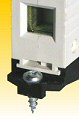
16. Superior Cover Design
The screws on the clip terminals are kept
from falling out
of the DPN body by our unique design.
The clip terminals are seated in the DPN casing so that the
screws of the terminals cannot fall out from the DPN body, even if
they are fully unscrewed from the terminal. This advantage has been reached
because the diameter of the hole at the plastic box (casing) for a screwdriver
is less than the diameter of the screw head. The screw head has been modified
both for cross and flat screwdrivers.
17.
ATTACHMENT EVEN ONTO DIN STRIPS WITH DIFFERENT THICKNESS
You will not be surprised by nonstandard
DIN strips
The DPNs are primarily intended to be attached on the strip DIN EN 50 022
(width - 35 mm, with the thickness range 0,8 - 2 mm). In the European market,
there are also the DIN strips outside the above range. The design of the movable
and fixed pawls of the DPN BONEGA® P-E-P allows attaching the devices even onto
less exact DIN strips.
top
18. A Pawl with Unique Characteristics
Quick installation and release.
The fastening mechanism with a movable pawl enables, as follows:
a) the DPN can be fastened to the DIN strip by a simple
“snapping”
-
Move the pawl from the B position into the A position (the
production position), if is has not been done yet.
-
Suspend the DPN in the upper on a projection on the DIN
strip’s upper part and snap it on the DIN strip’s bottom part with a
swinging motion.
b) the fast dismantling from the DIN strip
|
1
2
3
|
-
From the fixed condition in the position 3, move the pawl to
the Pos. 1 by means of e.g. screwdriver, which is to be put through the pawl
hole and to be drawn-half out.
-
The pawl keeps arrested in the Pos. 1 and the screwdriver
can be removed.
-
Now remove from the DIN strip.
The installation is essentially easier and faster with the DPN´s
BONEGA® P-E-P.
top
19. Extraordinary DPN's Body Strength
Extended mechanical reliability
|
The rigidity s given:
- By a highly sophisticated selection of a point for rivets
- By a number of rivets
- By the design of the case
|
20. ColoUred Control Levers
The colored levers increase the clear
arrangement and comply with the requirements of power-supplying plants.
We supply both the color version pursuant to the values of nominal currents
(which correspond to the indication of cap fuses) as a standard, and the black
version upon requirement.
|
6 A |
Green |
|
|
10 A |
Red |
|
|
13 A |
Sand |
|
|
|
16 A |
Grey |
|
|
20 A |
Blue |
|
|
25 A |
Yellow |
|
|
32 A |
Violet |
|
|
top
21. Sealing Under Certain Conditions
The ability to seal the lever in an ON
or OFF position.

|
The lever can be sealed because of openings in both guiding sidewalls of the
switch-off lever. Through these openings, a sealing wire can be fed. This
sealing wire passes also through a groove on the movable lever. This groove has
been engraved in OFF and ON positions and it disables the motion of the
lever itself.
If the lever is sealed in the ON position, the immobility does not render
the function of the DPN impossible. In the event of
short-circuit or overload, the circuit will be shutdown (independently on the
fixed position of the lever). The DPN case enables the lever to be sealed
independently on placing the adjacent DPN´s.
|
|
22. Smoother than any Switch you'll Find
You'll think it's not even on ...
The most excellent and balanced design of a switching mechanism. Extremely
easy running when switching-on the lever even in case of multi-pole models.
top
Export Manager: Michal Hudeček, tel: +420 605 518 724,
[email protected]
Sales Department: - Mrs Adriana Jamná,
fax +420 518 335 216, email : [email protected],
696 66 Sudoměřice nad Moravou 302