Superior security and protection
1. Extraordinary High-Speed Break
The sooner the entire
short-circuit process is terminated, the less damage there is
to connected devices
and wiring.
The BONEGA® P-E-P MCB's have reached the highest breaking
rate of any MCB (from 2 to 5 times higher than any other MCB).
An extraordinary high breaking rate beginning from the initiation of a
short-circuit to its termination amounts to max. 5 ms (with a maximum
load).
The BONEGA® P-E-P MCB's do not reach that high rate to the detriment of the
higher arc voltage which raises the risk of protected parts (e.g. motors)
considerably. As compared to other MCB´s, the arc voltage is equal or lower.
The high-speed switch-off consists of three stages:
- stage 1 – disconnection of contacts
- stage 2 – arc running into the chamber
- stage 3 – arc burning termination
The principal advantage of our MCB´s consists of an extraordinary high speed
within the first two stages. The third stage is very quick, as well, but it is
not so essential in the framework of the total speed. Within this last stage, it
is most essential that the chamber is so well constructed that the arc does not
“jump-out” in any direction (especially it does not come back to the contacts at
all).
An almost textbook run of the short-circuit process is caused also by the
suitable adjustment of the contact thrust. These contacts do not deviate by
the influence of aerodynamic forces (as obvious from the
charts).
Note: Some producers mention only the speed of contact disconnection (which is
the first stage) instead of the total breaking speed. In the moment of contact
disconnection, the power is still flowing through the circuit (voltage and
current) because of the created arc. In this stage, the MCB has not disconnected
the circuit yet.
Conclusion:
- Our curve of breaking procedure is fully unique (an example how an MCB should protect).
- The extremely
high breaking rate will not endanger the end user, but – in contrast – it
will protect him better
- The extraordinary breaking rate of the BONEGA® P-E-P MCB's provides the
most sensitive protection
of human lives, electrical devices within a circuit, and wiring itself.
More information: oscilograms and graphs
 to the top
2. Guaranteed Short-Circuit Resistance
The MCB's BONEGA® P-E-P
can be used under
the most difficult short-circuit conditions.
Our primacy consists in the breaking capacity of 10 kA up to the highest
value of 63A, even with the curve “D” pursuant to CSN EN 60898 (nobody has
reached it yet).
Our worldwide uniqueness consists in integration of the following
phenomena with the kept breaking capacity of 10 kA:
I.) It is necessary to be aware of that
the inside MCB´s resistance affects – inter alia – the breaking capacity.
With the low nominal values (e.g. 1A), almost every producer can pride
himself that his MCB theoretically has an unlimited breaking capacity.
The higher is the nominal current, the lower is the assistance of the inside
MCB´s resistance to absorb the short-circuit process. The nominal current
crucial value is at 25A MCB´s and the very critical ones is at the highest
value, i.e. 63A within the curve “D”. If the experts want to detect the MCB´s
quality, so they always use the aforementioned crucial values (25A and 63A).
Within these values, the design of the breaking mechanism, contacts,
extinguishing chamber etc. becomes known very clearly.
The essential difference, as compared to the MCB´s of
several producers, consists in the reached range of nominal currents,
which is reached with the mentioned breaking capacity (25 kA, 15kA, 10kA, 6kA
...). We are preparing the upper limit of the nominal currents, which can be
reached by our MCB´c within their breaking capacity 25 kA and 15kA.
II.) Another important difference consists in the standard, in
accordance with which the producer has achived his certification. In Europe,
there are two basic standards, namely:
a) the so-called „industrial“ standard CSN EN 60947
b) the so-called „household“ standard CSN EN 60898
As to their relations to breaking capacities, the standards differ e.g. in their
requirements of short-circuit quantity, which a MCB has to withstand without
disablement of its function. That means one short circuit pursuant to the
standard ČSN EN 60947 and three successive short-circuits pursuant to the
standard ČSN EN 60898.
As resulting from the above, the industrial standard is significantly softer.
For many people, that requirement of the standard seems to be illogical, but is
takes into consideration the behavior of a user, after the circuit has been
broken by a MCB. The reaction of the user in a household often is that he tries
to switch-on the MCB for the first, second and third time and just after that he
begins to trace the cause. In contrary, a professional electrician tries to
switch-on it only once and if the MCB breaks again, he begins to trace the cause
immediately.
III.) Take into account also the third significant difference – the
width of a MCB. There are some MCB´s with an even higher breaking capacity,
but they are in a 1,5-modular or double-modular design.
Notice at other producers, according to which standard and up to which
nominal current values they mention the breaking capacity. You can be
surprised by the results of worldwide-accredited producers.
The above parameters are caused by the distinguishing chamber, which is
one of our two worldwide-acknowledged Czech patents within the MCB P-E-P. Its
extraordinary properties could be seen also at the prepared DPN (there is a MCB
+ switch within one module of 17,5 mm). In this case, we have also overcame the
breaking capacity limitation of 4,5 kA which had been reached worldwide pursuant
to the standard ČSN EN 60898.
The MCBˇs with a short-circuit resistance up to 15 kA are tested now. As to
the single-modular design of those MCB´s (width 17,5 mm) and the given range
of nominal currents, we would be the only ones worldwide. The prepared MCB´s
BONEGA® P-E-P with the breaking capacity of 15 kA can find their application
especially in special works where they can replace the 1,5 or double modular
MCB´s.
3. Reduction of Undesirable Power During a Short-Circuit
The lower the power within a short-circuit,
the less damage to the connected devices
and wiring.
It is a very important property of a MCB, which is often marginalized by the
public.
The quality of the MCB protection is also conditioned by the amount of power
that “flows” through the MCB during short-circuit. Its amount is given by the
relation: E = I2.t.
As resulting from the mentioned relation, the high breaking rate of the MCB´s
BONEGA® P-E-P reduces that undesirable power.
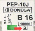
The standard CSN 60898+A1/A11 states the power limits based of which the MCB´s
are classified. The category (class) is mentioned on a MCB in the frame below
the breaking capacity.
Our MCB´s reach the limits of the 3rd (the highest possible) class without power
limitation pursuant to CSN 60898+A1/A11, namely even with the nominal breaking
capacity of 10 kA.
The following tables show the requirements of the standard for the MCB up to 16A
and above 16A up to 32A incl., at various nominal short-circuit capacities.
The power limiting class reached by a MCB is an essential element for
assessment of its protective function. We have met the third power limiting
class within the whole range requested (as one of few producers), even with the
rated short-circuit capacity of 10 kA. The following tables present e.g. the
standard requirements for the MCB up to 16 A, and above 16A up to 32A incl. with
different rated short-circuit capacities.
| Permitted values I2t for the MCB´s with the rated
current up to 16 A incl. |
| Rated short-circuit capacity
(A) |
Power limiting classes
|
|
1
|
2
|
3
|
|
max. I2t
A2s
|
max. I2t
A2s
|
max. I2t
A2s
|
|
type B a type C
|
type B
|
type C |
type B
|
type C |
| 3 000 |
The limits not stated
|
31 000 |
37 000 |
15 000 |
18 000 |
| 4 500 |
60 000 |
75 000 |
25 000 |
30 000 |
| 6 000 |
100 000 |
120 000 |
35 000 |
42 000 |
| 10 000 |
240 000 |
290 000 |
70 000 |
84 000 |
|
(the values written in bold digits are valid for our
MCB´s BONEGA®, series P-E-P):
|
| Permitted values I2t for the MCB´s with the rated
current above 16 A and up to 32 A incl. |
| Rated short-circuit capacity
(A) |
Power limiting classes
|
|
1
|
2
|
3
|
|
max. I2t
A2s
|
max. I2t
A2s
|
max. I2t
A2s
|
|
type B a type C
|
type B
|
type C |
type B
|
type C |
| 3 000 |
The limits not stated
|
40 000 |
50 000 |
18 000 |
22 000 |
| 4 500 |
80 000 |
100 000 |
32 000 |
39 000 |
| 6 000 |
130 000 |
160 000 |
45 000 |
55 000 |
| 10 000 |
310 000 |
370 000 |
90 000 |
110 000 |
|
(the values written in bold digits are valid for our
MCB´s BONEGA®, series P-E-P):
|
to the top
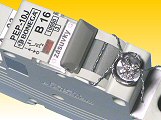
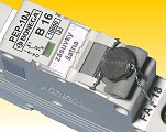
4. Locking Protection
The BONEGA® P-E-P
MCB´s cannot be locked from the outside.
|
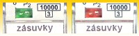
red I - ON
green O - OFF
|
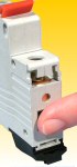
As the most products, also the MCB´s BONEGA® P-E-P has an
indication of the contact conditions. That indicates a real contact condition
and not only a position of the switch-on lever. In case of “sintered” contacts
and switched-off lever, the user is clearly informed about flowing current. As
the only ones, our MCB´s have that indication
|
Reasons:
- Because the indication is closely connected with a movable contact, it
happens on other MCB´s that the movable contact is locked through the
indication by means of a toothpick or a matchstick; thus the complete
thermal and short-circuit protection of a MCB is out of function. It is
not possible to do this on the MCB BONEGA® P-E-P, just because of that
transparent sight-glass
- Dust protection
This property protects the electro installation companies against
claims, which are caused by the end user, who can be proved wrong with
difficulties.
The philosophy of the colored indication ON/OFF is explained within
frequent questions.
5. Simultaneous Switching of the Multi-Module's
Connected devices are
less strained.
A worldwide unique recently patented system of triggering mechanism which
ensures a safe, more accurate and simultaneous switching of all the
contacts at multi-module (pole) miniature circuit breakers; it has been reached a three-times
longer switching distance than that reached by the best competitors world-wide.
This advantage enable e.g. continuous start of multi-fuse electric motors
(all fuses are switched at the same time).
to the top
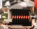
6. Revolutionary Designed Extinguishing Chamber
The extinguishing
chamber affects the breaking speed
and breaking capacity.
The extinguishing chamber is of a fully new patent-protected conception.
a) a very fast “drawing-in” of an arisen electric arc into the chamber
When the movable contact is disconnected from the fixed one, it is necessary
to “draw-in” the arisen arc into the extinguishing chamber as soon as possible
and to interrupt the circuit definitely. The MCB´s BONEGA® P-E-P do not reach
that high rate to the detriment of the higher arc voltage which rises the risk
of protected parts (e.g. motors) considerably. This could be reached e.g. by
higher number of sheets at the extinguishing chamber. Our chamber has only usual
13 interruptions. As compared to other MCB´s, the arc voltage within the MCB´s
BONEGA® P-E-P is equal or rather lower.
b) it is not possible the arc to return to the contacts
In other MCB´s, the arc can return to the contacts, so the circuit is connected
again. Thanks to the design of the chamber, this phenomenon is not possible in
the MCB´s BONEGA® P-E-P.
c) fast arc extinction
The sooner the arc is extinguished, the smaller amount of heat arises. This
heat can affect the adjacent circuits (warming of an adjacent MCB)
d) utilization of cold air at the extinguishing chamber for cooling the
contacts
At the beginning of short-circuit process, the non-warmed air inside the
chamber is used for cooling the contacts immediately before they are
disconnected
7. Durability
Impact resistant.
|
The design of the electromagnetic high-speed release with ejecting armature
for short-circuit protection has been solved so that it has not any adjustable
element. The characteristic is given by the cross-section of the copper wire of
the coil, by number of threads and spring pre-stressing in the core. This
solution thus excludes that our circuit breakers could change their presented
value by a fall or shock.
to the top
|
8.
Terminal Resistant to Inter-Phase Short-Circuit
MCB BONEGA® P-E-P
eliminates danger of inter-phase short-circuit e.g. just by air ionization.
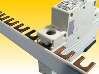
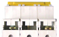
At the upper part of the terminal (serving for interconnection by means of
forked strip), the MCB´s body is equipped with partitions which can be broken of.
Those partitions shall avoid a possible inter-phase short-circuit in case of
interconnection of multi-module types by means of multi-phase interconnecting
strips. This short-circuit can be caused by air ionization or humidity, that
support electric arc.
9. Vibration Resistance
The BONEGA® P-E-P
MCB´s can be used in equipment with strong vibrations (e.g. railway wagons, site
switchboards).
Strong vibrations can cause the short-circuit release to be put out of service
(it loses its protective function) or the spot-welds to be disconnected (current
interruption).
a) measures avoiding the short-circuit release to be put out of service
|
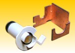
The MCB´s BONEGA® P-E-P are protected against the above phenomenon by a
suitable seating of the structure elements, especially of the ejecting coil
which is seated in a unique “cradle” (see the Fig.). This design has excluded
the possibility to misalign and consequently to seize the movable core at the
coil. |
b) measure avoiding the spot welds to be disconnected
The quantity of spot-welds can be reduced significantly. The elements are
interconnected by means of a modular design, or he parts are made of one piece.
to the top
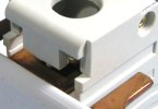
10. Protection Against Hacking of an MCB
We comply with the
requirements of distribution
companies for disassembly protection.
The multi-pole MCB´s BONEGA® P-E-P cannot be disassembled in such a way that
only the interconnection between stretching levers would be removed and the
individual poles could function separately (e.g. through this, the day and night
tariff rate could be influenced). Especially the distribution companies call for
this property.
The mutual phases interconnection does not happen just between the levers, but
also by means of pins which are put between the pole and they interfere directly
into the inside mechanisms through a side hole. In addition, the multi-pole
design is connected with rivets. The interconnecting and covering strip, which
is between the levers, is visibly depreciated. Any interference in a MCB
is obvious at first sight.
11. Higher Safety Standards
Construction of the cover
eliminates electrical current injury
caused by touching the circuit breaker.

All locking bars are protected against danger touch and penetration of
small foreign objects (IP protection 20).
to the top
12. Wide Selectivity
The MCB´s can be used
within combined projects.
The selectivity means a coordination of two successive
breaking devices so that just the disabled wiring part can be switch-off upon a
failure. A wide scale of current values and curves B, C and D
enables our MCB´s to be put together to various safety cascades. Because of the
above, the desired selectivity can be reached.
13. Colored Control Levers
The colored levers
improve the transparency and comply with the requirements of power plants.
We supply both coloured levers in accordance with the nominal current
values (corresponding to the marking of turn fuses) and black levers.
|
0,2 A - 1,6 A |
black |
|
|
2 A |
pink |
|
|
4 A |
brown |
|
|
6 A |
green |
|
|
8 A |
light green |
|
|
10 A |
red |
|
|
13 A |
sandy |
|
|
|
16 A |
grey |
|
|
20 A |
blue |
|
|
25 A |
yellow |
|
|
32 A |
purple |
|
|
40 A |
black |
|
|
50 A |
white |
|
|
63 A |
copper-coloured |
|
|
14. Sealing Under Certain Conditions
The ability to seal the
lever in an ON or OFF position.
|
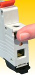
The lever can be sealed because of openings in both guiding sidewalls of the
switch-off lever. Through these openings, a sealing wire can be fed. This
sealing wire passes also through a groove on the movable lever. This groove has
been engraved in OFF and ON positions and it disables the motion of the
lever itself.
If the lever is sealed in the ON position, the immobility does not render
the function of the circuit breaker impossible. In the event of
short-circuit or overload, the circuit will be shutdown (independently on the
fixed position of the lever). The MCB case enables the lever to be sealed
independently on placing the adjacent MCB´s.
|
to the top
|
Export Manager: Michal Hudeček, tel: +420 605 518 724,
[email protected]
Sales Department: - Mrs Adriana Jamná,
fax +420 518 335 216, email : [email protected],
696 66 Sudoměřice nad Moravou 302