Technical parameters
Description of the water-meter
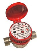
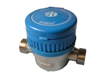
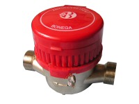
The BONEGA® water-meter - S(A)/13 (20) or T(A)/13 (20) is a single-inlet
blade household water-meter with internal slide control and dry-running counter,
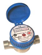
with a wheel for photometric reading. The water-meter is intended mainly for the
cold and warm drinking water. The water-meter level on a drum counter can be
read with an accuracy of 1 liter. The water-meters are manufactured in a
standard and special version with antimagnetic protection.
Key:
S = standard cold-water
water-meter up to the temperature 30°C
T = standard warm-water
water-meter up to the temperature 90°C
SA = water-meter with the high
antimagnetic resistance – for cold water up to the temperature 30°C
TA = water-meter with the high
antimagnetic resistance – for warm water up to the temperature 90°C
These household water-meters are
intended to measure the flow-rate and the flown-through as a working meter in
terms of Act No. 50/1990 Col., as amended.
The water-meter is constructed to measure the water consumption especially at
the flats – for installations into the water piping by means of couplings –
screw joints. It can be joined to the piping with the nominal clearance 15 mm
(1/2”) or 20 mm (3/4”) and for maximum short-term operating overpressure up to
1,6 MPa.
The water-meter’s parts and measurement principles
The single-inlet dry-running cold-water water-meter BONEGA® consists of the
measuring wet-running part (the blade mechanical flow-rate indicator) and
the dry-running indicating device (mechanical counter).
Wet-running part
The wet-running part of the
water-meter consists of the brass body with connecting threads. The body and the
cover form a measuring space, in which the measuring rotor rotates. The
water-meter’s blade wheel with five blades is bedded in two bearings. The
flowing water is directed by two slides (the bottom and the upper one) which are
controlled by rotating the upper slide board. The wet-running part is coupled
with the dry-running counter by a magnetic coupling. The counter is not in
contact with the liquid.
The system’s water flows through the
meter from the inlet where it hits the meter’s turbine and causes its rotation,
and flows away to the outlet. The turbine motion is transmitted onto the counter
by a magnetic coupling. This solution avoids the mechanical interconnexion of
the turbine and the counter. Such interconnexion could cause water to leak
around the shaft into the space outside the counter. The turbine is thus the
only one movable part that is in direct touch with the water.
Dry-running part
Based on a mechanical principle, the
dry-running part of the water-meter registers and displays the amount of
flown-through water. The indicating device consists of a combination of roller
counter (5 lines with black digits displaying the flown-through volume in m3 and
3 lines with red digits displaying tenths, hundredths and thousandths of m3 )
and a round display with red pointer for indication of ten-thousandths . The
digits displaying the flown-through volume in m3 are 4 mm high and they move
vertically upwards. The movement of the digits is finished at the moment when a
digit of the nearest lower decade is changing from 9 to 0. The counter is fitted
with a rose for opto-electronic (photometric) scanning of revolutions.
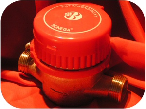
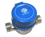
The counter is fastened and
tightened with an irremovable sealing fastening ring in red color for warm
water-meters and blue color for cold water-meters.
The outside surface of the body is nickel-coated for the anti-corrosive
resistance and better appearance – it is the best corrosion protection (the
inside surface of the body is not nickel-coated for the hygienic reasons).
The application of water-meters for drawing-up charges for water supply enables
to objectify the relations between suppliers and customers and to increase the
customer’s interest in water economy.
Comparison with others
The BONEGA household water-meter complies
with ISO 40 64.1, class B and CSN 257801
Based on a thorough comparison of the measurement accuracy of
the best selling dry-running water-meters in the Czech Republic and after a
random purchase of the water-meters in shops, the calibration facility Brněnské
vodárny a kanalizace has arrived at the conclusions that the BONEGA®
water-meters are the most accurate and sensitive water-meters within their class.
The executed measurements have showed that our water-meters could be included
within the higher C class with no problems. The start of the BONEGA®
water-meters begins as early as with the flow-rate under 8 l / h whereby the CSN
257801 and CSN 736622 standards require the start with the flow-rate 30 l/h for
the household water-meters of the class “B” and 15 l/h for the class “C”.
With their highest measurement accuracy, the BONEGA®
water-meters can significantly help to refute the doubts about the accuracy of
water ratio measurement at the flats.
Specifications and common data
|
BONEGA® water-meters |
|
DESCRIPTION
|
UNIT
|
SPECIFICATIONS AND DIMENSIONS |
|
Nominal clearance DN |
mm
inch |
13
1/2" |
20
3/4" |
Overloading flow-rate – given by the standard
Qmax "Qs"- maximum peak capacity (short-term – maximum 1 hour per day) –
within the second accuracy limit, it has to have the max. deviation ± 2 % |
m3/h |
3 |
5 |
Nominal flow-rate – given by the standard
Qn - nominal (permanent, usual, nominal) flow-rate - within the second
accuracy limit, it has to have the max. deviation ± 2 % |
m3/h |
1,5 |
2,5 |
Minimal flow-rate – given by the standard
Qmin – the first accuracy limit has to have the deviation ± 5% |
liters/h |
30 |
50 |
|
Real starting flow-rate |
liters/h |
5-8 |
|
Transition flow-rate – given by the standard
Qt - the second accuracy limit has to have the deviation ± 2 % |
liters/h |
120 |
200 |
|
Max. operating pressure on the water-meter place
|
MPa |
1,6 |
|
∆P with Qmax. (pressure drop with Qmax)
|
MPa |
0,074 |
0,096 |
|
Counter capacity (maximum reading ) |
m3 |
100 000 |
|
Value of a scale graduation (minimum reading) |
liters [dm3] |
0,05 |
|
L1 – installation length without screw joint (for installation, a
clearance for packing has to be added)
|
mm |
110 |
130 |
|
L2 – water-meter length with seated screw-joint |
mm |
170 |
205 |
|
L3 - water-meter length with non-seated screw-joint
|
mm |
190 |
228 |
|
Length of a screw-joint thread |
mm |
14 |
16 |
|
H(s) – height without plastic lid for standard design (for antimagnetic
design in the brackets) |
mm |
68 (78) |
|
H(a) – height with plastic lid for standard design (for antimagnetic
design in the brackets) |
mm |
75 (85) |
|
B(š) – width without plastic lid (with the lid)
|
mm |
75 (80) |
|
Water-meter attachment (D) |
inch |
G 3/4“ |
G 1“ |
|
Thread connection on the water-meter (d) |
inch |
KG 1/2“ |
KG 3/4“ |
|
Weight (without connections = screw joint) for standard design (for
antimagnetic design in the brackets)
|
kg |
0,55(0,70) |
0,65(0,80) |
|
Metrological class in horizontal position |
ISO |
B |
|
Metrological class in vertical position |
ISO |
B |
|
Maximum operating temperature for cold and warm water S/T |
°C |
30/90 |
|
Pulse number |
pulses/litr |
225 |
142,548 |
|
Revolutions of photometric disc |
rev/100 liters |
1.125,00 |
712,74 |
|
Turbine revolutions with the flow-rate 100 l |
rev/100l |
3.037,5 |
1.924,4 |
|
Nominal volume per one revolution of blade wheel |
cm3 |
32,922 |
51,964 |
|
Number of teeth – turbine |
ks |
10 |
10 |
|
Number of teeth – transmission wheel 1 |
ks |
8/27 |
11/27 |
|
Number of teeth – transmission wheel 2 |
ks |
10/30
|
10/28 |
|
Number of teeth – transmission wheel 3 |
ks |
30 |
28/30 |
|
Copper content in water-meter’s brass body |
% |
57 |
57 |
weights
|
|
1/2" a 3/4" water-meters BONEGA® for cold water
up to + 30 °C
|
|
Order Code |
Clearance (mm-inch) |
Installation length (mm) |
Nominal flow-rate Qn (m3/h) |
|
1/2" BONEGA-S/13-110-1,5-B |
13-1/2" |
110 |
1,5 |
|
3/4" BONEGA-S/20-130-2,5-B |
20-3/4" |
130 |
2,5 |
|
Packaging: 20 pc. water-meters, packed separately in paper labeled
cases, in one box.
Box dimensions for 1/2" water-meters - w. 27 cm x h. 19 cm x d. 45 cm
Box dimensions for 3/4" water-meters - w. 31 cm x h. 19 cm x d. 45 cm
Case dimensions for 1/2" water-meters - 120 x 85 x 80 mm
Case dimensions for 3/4" water-meters - 140 x 85 x 80 mm
| Hmotnost |
1/2" netto = 0,55 kg/pc (single without package) |
(box gross 12,210 kg) |
| 3/4" netto = 0,65kg/pc (single without package) |
(box gross 14,500 kg)
|
| only case for 1/2" |
0,035 kg |
| only case for 3/4" |
0,045 kg |
| only box for 1/2" |
0,510 kg |
| only box for 3/4" |
0,600 kg |
|
|
|
|
1/2" a 3/4" water-meters BONEGA® for warm water up
to + 90 °C |
|
Order Code |
Clearance (mm-inch) |
Installation length (mm) |
Nominal flow-rate Qn (m3/h) |
|
1/2" BONEGA-T/13-110-1,5-B |
13-1/2" |
110 |
1,5 |
|
3/4" BONEGA-T/20-130-2,5-B |
20-3/4" |
130 |
2,5 |
|
Packaging: 20 pc. water-meters, packed separately in paper
labeled cases, in one box.
Box dimensions for 1/2" water-meters - w. 27 cm x h. 19 cm x d. 45 cm
Box dimensions for 3/4" water-meters - w. 31 cm x h. 19 cm x d. 45 cm
Case dimensions for 1/2" water-meters - 120 x 85 x 80 mm
Case dimensions for 3/4" water-meters - 140 x 85 x 80 mm
| Hmotnost |
1/2" netto = 0,55 kg/pc (single
without package) |
(box gross
12,210 kg) |
| 3/4" netto = 0,65kg/pc (single
without package) |
(box gross
14,500 kg)
|
| only case for 1/2" |
0,035 kg |
| only case for 3/4" |
0,045 kg |
| only box for 1/2" |
0,510 kg |
| only box for 3/4" |
0,600 kg |
|
|
|
|
Weights OF 1/2" a 3/4" water-meters BONEGA® for
cold water up to + 30 °C with antimagnetic treatment |
|
Order Code |
Clearance (mm-inch) |
Installation length (mm) |
Nominal flow-rate Qn (m3/h) |
|
1/2" BONEGA-SA/13-110-1,5-B |
13-1/2" |
110 |
1,5 |
|
3/4" BONEGA-SA/20-130-2,5-B |
20-3/4" |
130 |
2,5 |
|
Packaging: 20 pc. water-meters, packed separately in paper
labeled cases, in one box.
Box dimensions for 1/2" water-meters - w. 27 cm x h. 21 cm x d. 45 cm
Box dimensions for 3/4" water-meters - w. 31 cm x h. 21 cm x d. 45 cm
Case dimensions for 1/2" water-meters - 120 x 95 x 80 mm
Case dimensions for 3/4" water-meters - 140 x 95 x 80 mm
| Hmotnost: |
1/2" netto = 0,70 kg/pc (single without package) |
(box gross 15,355 kg) |
| 3/4" netto = 0,80 kg/pc (single without package) |
(box gross 17,540kg)
|
| only case for 1/2" |
0,040 kg |
| only case for 3/4" |
0,045 kg |
| only box for 1/2" |
0,555 kg |
| only box for 3/4" |
0,640 kg |
|
|
|
|
Weights OF 1/2" a 3/4" water-meters BONEGA® for
warm water up to + 90 °C with antimagnetic treatment |
|
Order Code |
Clearance (mm-inch) |
Installation length (mm) |
Nominal flow-rate Qn (m3/h) |
|
1/2" BONEGA-TA/13-110-1,5-B |
13-1/2" |
110 |
1,5 |
|
3/4" BONEGA-TA/20-130-2,5-B |
20-3/4" |
130 |
2,5 |
|
Packaging: 20 pc. water-meters, packed separately in paper
labeled cases, in one box.
Box dimensions for 1/2" water-meters - w. 27 cm x h. 21 cm x d. 45 cm
Box dimensions for 3/4" water-meters - w. 31 cm x h. 21 cm x d. 45 cm
Case dimensions for 1/2" water-meters - 120 x 95 x 80 mm
Case dimensions for 3/4" water-meters - 140 x 95 x 80 mm
| Hmotnost: |
1/2" netto = 0,70 kg/pc (single without package) |
(box gross 15,355 kg) |
| 3/4" netto = 0,80 kg/pc (single without package) |
(box gross 17,540kg)
|
| only case for 1/2" |
0,040 kg |
| only case for 3/4" |
0,045 kg |
| only box for 1/2" |
0,555 kg |
| only box for 3/4" |
0,640 kg |
|
|
|
|
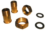
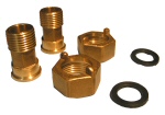
Brass screw joints with a hole incl. packing -with two pieces in a set) |
|
Order Code |
Type of screw joints |
|
1/2" BONEGA®- MS - OT |
A screw joint set for ½” water-meters (2x ¾” cap nut 30 mm with holes
for possible sealing, 2x sleeve with hexagon 20 mm, 20 mm, 2 x packing) |
|
3/4" BONEGA®- MS - OT |
A screw joint set for 3/4 " water-meters (2 x 1" cap nut 37 mm with
holes for possible sealing, 2x sleeve with hexagon 24 mm, 2 x packing) |
Packaging: a set, single packed in a polyethylene bag
Weight:
1/2" net = 0,175 kg/set
3/4" net = 0,285 kg/set
|
|
|
|
Brass screw joint with “eye” incl. packing (two pieces in a set) |
|
Order Code |
Type of screw joints
|
|
1/2" BONEGA®- MS - OU |
A screw joint set for ½” water-meters (2x ¾” cap nut 30 mm with “eyes”
for possible sealing, 2x sleeve with hexagon 20 mm, 20 mm, 2 x packing) |
|
3/4" BONEGA®- MS - OU |
A screw joint set for 3/4 " water-meters (2 x 1" cap nut 37 mm with
holes for possible sealing, 2x sleeve with hexagon 24 mm, 2 x packing) |
Packaging: a set, single packed in a polyethylene bag
Weight:
1/2" net = 0,175 kg/set
3/4" net = 0,285 kg/set
|
|
Sketches
|
VIEW (WITHOUT BOTTOM BOARD)
|
DIAL
|
|
|
|
TRANSMISSION SYSTEM
|
TRANSMISSION SYSTEM
|
|
|
|
|
COUNTER
|
|
Č. |
DESCRIPTION |
MATERIAL |
|
11.I |
SHAFT |
STAINLESS STEEL |
|
11.II |
LAST WHEEL WITH DIGITS |
ABS |
|
11.III |
PINIONS FOR THE WHEEL WITH DIGITS |
ABS |
|
11.IV |
MIDDLE WHEELS WITH DIGITS |
ABS |
|
11.V |
FIRST WHEEL WITH DIGITS |
ABS |
|
11.VI |
PHOTOMETRIC ROSE (FOR PULSE READINGS) |
POLYETHYLENE |
|
11.VII |
MAGNET |
MAGNETIC ALLOY |
|
11.VIII |
CENTRAL TRANSMISSION WHEEL |
POLYETHYLENE |
|
11.IX |
TRANSMISSION WHEEL # 1 |
POLYETHYLENE |
|
11.X |
BOTTOM BOARD |
NORYL 731 |
|
11.XI |
TRANSMISSION WHEEL # 2 |
POLYETHYLENE |
|
11.XII |
TRANSMISSION WHEEL # 3 |
POLYETHYLENE |
|
XI.13 |
CONTINUOUS TRANSMISSION WHEEL |
POLYETHYLENE |
|
XI.14 |
RED POINTER |
POLYETHYLENE |
|
XI.15 |
UPPER BOARD |
NORYL 731 |
|
TEETH OF TRANSMISSION WHEEL AND TURBINE REVOLUTIONS |
|
Qn |
Turbine |
Transmission wheel No. 1 |
Transmission wheel No. 2 |
Transmission wheel No. 3 |
Turbine revolutions /
100 l |
|
1,5 |
10 |
27 |
30 |
30 |
3037,5 |
|
2,5 |
10 |
27 |
28 |
28/30 |
1924,4 |
 Diagram
of the water-meter
Diagram
of the water-meter
1) Nickel-coated brass body
2) Turbine + magnet + spindle + ruby bearing
3) Main shaft (spindle) made of stainless steel
4) Bottom regulating board
5) Upper regulating board with ruby bearing
6) Tightening "O"-ring underneath the upper regulating board
7) Plastic sieve
8) Delimitating plastic ring
9) Brass securing nut
10) "O"-ring for counter tightening
11) Separate transparent lid
12) Removable protective plastic lid
13) Counter device
14) Securing ring