| List of content |
|
|
|
 The
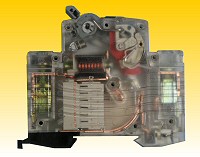
extraordinary small dimensions (especially the height is only 81 mm) rank the
DPN BONEGA® P-E-P to the smallest ones worldwide within the category of the
breaking capacity up to 6 kA.
The
extraordinary small dimensions (especially the height is only 81 mm) rank the
DPN BONEGA® P-E-P to the smallest ones worldwide within the category of the
breaking capacity up to 6 kA.
In the switchboard (in the covered part), remains more space for leading and connecting of conductors. This property can be appreciated especially when using those DPN in small plastic household switchboards.
The DPN BONEGA® P-E-P has two different releases acting onto the switching mechanism::
|
1.) Thermal over-current release for overcurrent protection, working with time lag |
| 2.) Electromagnetic high-speed release with ejecting cage for immediate short-circuit protection |
They are suitable especially for common installation into
switchboards and switching points of low-voltage end circuits. They are
designed mostly for alternating current. If you require using them for direct
current, please, contact our technical support.
They bear the logo with the trademark BONEGA® . It is a traditional brand
since 1992. The name BONEGA®comes from the ESPERANTO language and in that
language, BONEGA®means excellent, good.
They are manufactured in accordance with a particular European standard CSN EN 60898, as amended. They are able to comply with any design requirements for arrangement of DPNs with regard to the selectivity and requirements for individual characteristics B and C.
|
|
- the product complies with the conditions necessary for evaluation if our product conforms to the Czech rules |
|
|
- the product complies with the European conditions for Declaration on Conformity |
|
|
- the product has received the SEMCO Certificate |
|
|
- the product has received the KEMA Certificate |
The DPNs allow the plentiful accessories (low-voltage releases, voltage releases, auxiliary contacts etc.) to be linked very easily. In this way, its application can be extended to overvoltage or undervoltage protection, control, regulation, remote control, remote indication of switch-on and switch-off positions of the DPN, programming and measurement etc. The aforementioned combinations allow application in the range of control within difficult automation processes.
These accessories can be mutually interconnected (e.g. DPN + low-voltage release+ auxiliary indication contact etc.) and can form various combinations.
|
Technical data |
|||
| Number of poles: | 1 | ||
| Nominal currents ln (A): | 6,10,13,16,20,25,32 | ||
| Characteristics: | B (or L), also “V” before. The short-circuit release is to be set up to 3 ln through 5 ln. It serves especially for protection of circuits with such devices which do not cause any current surges (lights or socket circuits etc.) | ||
| C (or U), also K before. The short-circuit release is to be set up to 5 ln through 10 ln. It serves especially for protection of circuits with such devices which cause some current surges (groups of bulbs, motors etc.) | |||
| Nominal voltage: | ~ 230 V 50/60 Hz | ||
| Rupturing capacity: | EN 60898 - 6.000 A | ||
|
Protection:
|
IP 20 for a sole DPN - with its design, it protects against a hazardous finger touch as well as against small foreign objects; it is without any protection against water leakage ( water protection is to be solved with design of the switchboard casing ) | ||
| IP 40 for a built-in DPN - with its design, it protects against a hazardous finger or instrument touch as well as against very small foreign objects; it is without any protection against water leakage ( water protection is to be solved with design of the switchboard casing ) | |||
| Minimum ambient temperature: | - 40 ºC | ||
| Maximum ambient temperature: | +125 ºC | ||
| Operation temperature: | - 5 ºC to +40 ºC pursuant to ČSN EN 60898 | ||
| Gauging temperature: | +30 ºC pursuant to CSN (it is possible to agree upon different temperature) | ||
| Max. pre-inserted fuse: | 100 A gG (>10 kA) | ||
| Mechanical lifetime: | >= 20.000 cycles | ||
| Electrical lifetime: | >= 8.000 cycles | ||
| Operational position: | arbitrary | ||
| Fastening: | by means of an unique snap mechanism (with arrestment in final positions) the carrying DIN strip EN 50022, width 35 mm, or even onto the flat surface by means of screws | ||
| Removal from the DIN strip | by means of an unique auxiliary snap mechanism; the DPN's can be removed even from a row of devices mutually interconnected by a forked or reed (rack) strip without necessity to dismantle the whole interconnecting strip | ||
| Input terminals: |
- clip terminals (with barrier layer), snap- locked against the worse
input of a conductor - the input and output can be interchanged - they enable more conductors as well as interconnecting strips to be connected |
||
| Connectability of conductors (maximum cross-sections): | 16 mm2 solid conductor, 11 mm2 stranded conductor | ||
| Terminal protection: | IP 20 | ||
| Tightening moment for terminals: | 2 Nm (combined slotted-head screw) | ||
| Manufactured according to the standard: | ČSN EN 60898 | ||
| Power limiting class | 3 | ||
| Switch-off speed (see oscilograms): | under 10 ms | ||
|
For better distinction among circuits in the switchboards, we supply DPNs with distinction of nominal currents by means of colored levers corresponding to the colours of turn fuses:
|
6 A | green | |
| 10 A | red | ||
| 13 A | sand | ||
| 16 A | gray | ||
| 20 A | blue | ||
| 25 A | yellow | ||
| 32 A | violet | ||
| Can be delivered also with only black levers | 1-63 A | black | |
| Nominal current of DPN (A) | Internal resistance (mOhm) | Power loss (W) | Max. imped. Of impend.loop (Ohm) | Thermal correction of nominal currents | |||||
| Char. B | Char. C | Char. D | Ambient temper. 20°C | Ambient temper. 30°C | Ambient temper. 40°C | Ambient temper. 50°C | |||
| 6 | |||||||||
| 10 | |||||||||
| 16 | |||||||||
| 20 | |||||||||
| 25 | |||||||||
| 32 | |||||||||
| THERMAL RELEASE – SWITCHING-OFF CHARACTERISTICS PF DPN | ||||||
| Test | Type | Trial current |
Initiative condition |
Limits of switching-off or not-switching-off time | Reached result |
Notes |
| a | B,C,D | 1,13 In | cold* | t ≥ 1 h ( In ≤ 63 A) | must not switch-off | |
| b | B,C,D | 1,45 In | Immediately after test a | t < 1 h ( In ≤ 63 A) | must switch-off | The current constantly going up during 5 sec. |
| c | B,C,D | 2,55 In | cold * |
1s < t < 60 s ( In ≤ 32 A) 1s < t < 120 s ( In > 32 A) |
must switch-off | |
| d |
B C D |
3 In 5 In 10 In |
cold* | t ≥ 0,1 s | must not switch-off | Current reached by switching-on the auxiliary contact |
| e |
B C D |
5 In 10 In 20 In |
cold* | t < 0,1 s | must switch-off | Current reached by switching-on the auxiliary contact |
* the „cold condition “ means without previous loading during reference gauging temperature
|
|
|
Products | About us | Customer support | Become our partner | Certificates & declarations | Contacts | Site map |
|
|
 1.
1.